In an attempt to better understand the effect of temperature and humidity in weather forecasting, I decided to build a small thermometer with an Arduino and a temperature sensor. In a future article, I will explore some of the data that I capture and the software that analyzes the data. This article will focus on the thermometer.
Parts
For this project, I used the following parts:
- An Arduino Uno
- Breadboard
- Jumper wires
- 10 kΩ resistor
- Kuman 0.96” I2C OLED display (128x64)
- OSEPP-HUMI-01 temperature and humidity sensor
Note that there are many other displays and sensors designed to work with the Arduino. You may need to adjust the pin layout and resistor value depending on what you use.
Wiring Schematic
The schematic for the circuit itself is fairly simple:
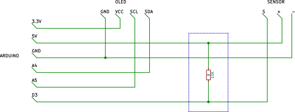
It is possible to connect the OLED display to 5V instead of 3.3V but this configuration saves a couple of wires. The 10 kΩ pull-up resistor connects 5V to digital pin 3.
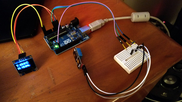
When finished, the thermometer should look something like this:
Libraries
In order to interact with the OLED display and sensor, you will need the following libraries:
- adafruit/Adafruit_Sensor
- adafruit/DHT-sensor-library
- adafruit/Adafruit-GFX-Library
- adafruit/Adafruit_SSD1306
The first two are for the sensor and the second two are for the OLED display.
You will need to complete one additional step after installing the libraries. Browse to the Adafruit_SSD1306 directory and uncomment the following line in Adafruit_SSD1306.h:
#define SSD1306_128_64
Make sure that the two lines that follow it are commented out:
//   #define SSD1306_128_32
//   #define SSD1306_96_16
Program
At long last, we are ready to write the program. Begin the program by including the necessary headers:
#include <DHT.h>
#include <Adafruit_SSD1306.h>
#include <Fonts/FreeSans12pt7b.h>
DHT.h provides access to the sensor and Adafruit_SSD1306.h is for the display. The font is not strictly necessary but greatly improves the readability of the text displayed.
Next, create an instance of DHT which will be used to read the sensor values and Adafruit_SSD1306 which will be used to interact with the display:
#define DHTPIN 3
#define DHTTYPE DHT11
DHT dht(DHTPIN, DHTTYPE);

#define OLED_RESET 4
Adafruit_SSD1306 display(OLED_RESET);
The following snippet is not necessary but acts as a safeguard in case SSD1306_128_64 was not commented out as described above.
#if (SSD1306_LCDHEIGHT != 64)
#error("Height incorrect, please fix Adafruit_SSD1306.h!");
#endif
The setup for the program is very simple - the display needs to be initialized:
void setup()
{
  display.begin(SSD1306_SWITCHCAPVCC, 0x3C);
  display.setTextColor(WHITE);
  display.setFont(&FreeSans12pt7b);
}
The loop is broken down into three parts: obtaining sensor values, formatting them, and displaying the result. A char array is used to store the message that will eventually be displayed onscreen:
void loop()
{
  // Storage for the message to be shown on the display
  char szDisp[128];

  // Read the data from the sensor
  float fTemp = dht.readTemperature();
  float fHum = dht.readHumidity();

  if (isnan(fTemp) || isnan(fHum)) {
    sprintf(szDisp, "err: sensor");
  } else {
Because sprintf() doesn’t format floats, we need to use dtostrf() to store them in a char array:
    // Convert the floats into strings
    char szTemp[8];
    char szHum[8];
    dtostrf(fTemp, 1, 1, szTemp);
    dtostrf(fHum, 1, 1, szHum);

    sprintf(szDisp, "T: %s C\nH: %s%%", szTemp, szHum);
  }
Lastly, clear the display, position the cursor, and print the message:
  // Show the computed value
  display.clearDisplay();
  display.setCursor(0, 20);
  display.println(szDisp);
  display.display();

  // Values can only be read from the sensor every two seconds
  delay(2000);
}
You can find a complete copy of the source code in this Gist.